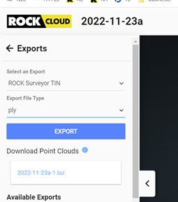
I am after the resulting bare earth surface after processing that is utilized to create final contours. I see I can export the contours(vectors) as dxf and that works great. But how do I export a representation of the bare earth surface that is utilized to create the contours? I see that I can export the Surveyor Tin to a .ply file. I am not familiar with how I could get that to a standard format. Would it be possible to get that TIN to kick out as a dxf with the TRImesh exposed? Or a workflow that would allow me to get that .ply file to some sort of standard mesh file I can bring into CAD. Thanks
Got the dem into c3d importing as surface. Thanks! I am still not sure how to work with such a dense file type in our standard survey work flows. Surveyors work with TINs(irregular network). I cant figure out how to get a dem to a lightweight version that is not just a grid that would not represent any ground break lines anyway. I hear you might eventually allow a xml export…what would that consist of? Just a symmetrical point and mesh based grid, or would it produce more of a traditional TIN?
Do you have a similar process of how I can convert the the PLY to make it easier when I deliver file packages to engineers for them to import into autocad? I mainly use arcgis pro and I keep getting requests for landxml.
Would love to see XMLs on the list of deliverables. We use XML files almost exclusively in Civil 3D for dealing with LAS files. 2013 was the last year that Autodesk allowed us to directly import LAS files into Civil 3D, since then Land desktop XMLs are key to our workflow.
What’s your workflow for turning the ROCK lidar data into landXML? Right now, I have survey tech that can do it for me on specific projects that the surveyor doesn’t know how to do themselves! So it’s okay for now, but I know he won’t be around forever to me to sub the work out.
I mean I export the surface into a point grid or something that the surveyor wants. If they need it in XML I’ll build it with a workflow (varies by client) to get a surface/contours in CAD and then I can export a XML from Civil 3D from that data pretty easily. It just would be nice to be able to export straight from Rock Cloud to save some steps but also ensure some consistency in how a surface is built. There a lot of options when building a surface in CAD and if you don’t know what your doing you can get errors just in how you build the TIN…
Agree. I do the same thing, just export points or contours to CAD, then blend with field shots, then create the surface. DEFINETELY requires you do know what you’re doing.
We’re working on it! It’s just…much harder than it looks.
Another option is to open the PLY in “CloudCompare” free software and then SAVE the PLY as a MESH.dxf for import into Carlson Software w/IntelliCad engine or AutoCAD. The surveyor on a 30 acre site used 22 check points vs the mesh and the worst point was 0.24’ difference but the average of all points on the mesh was less than 0.1". He was happy!
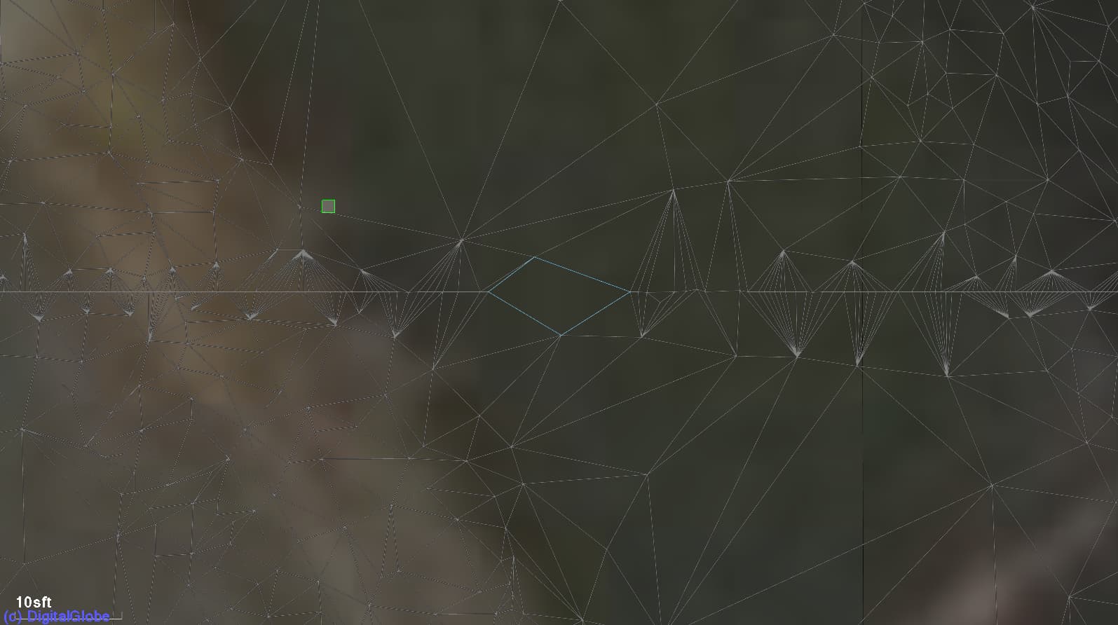
Seemed to work quite nicely when exporting an older file. Haven’t done any accuracy comparisons but there were a few small holes in the XML model that the contours just interpolated when building it from scratch. I’ll make a new post with a comparison in a few weeks after we get through a few projects with it.
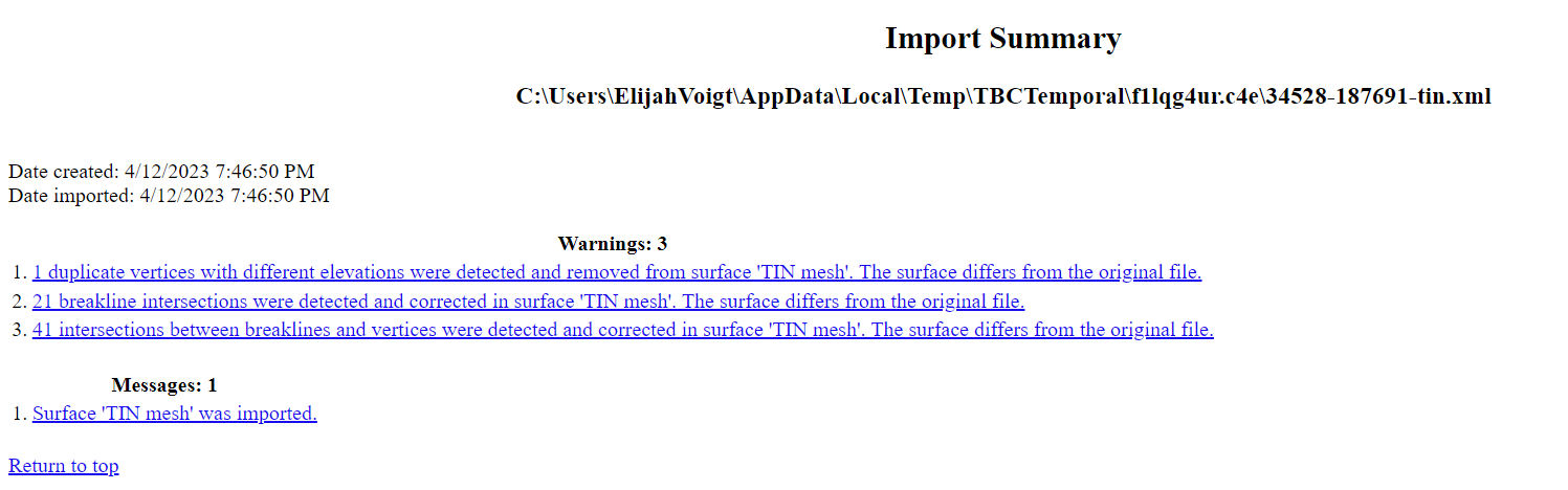
Very happy to see this option available. I also see some holes in the TIN once imported. They look isolated to the stitching lines. When importing into TBC I do get some errors. Carlson will not seem to accept the xml at this time. Acts like it is importing and does not import.