Hello Rock community! Looking for advice on this project. Planning to fly a long oval track. Track measures 4,000ft long and 1,000 ft wide. Trees in the infield and trees around the outside. I am most interested in capturing the asphalt track only. Should I still setup a grid mission or somehow manually fly the track using the M300 fpv camera.
Any advice would be greatly appreciated!
It depends on if you want to capture the entire thing or not?
Considering that is less than 100 acres in size I don’t think it would be too much trouble to do the entire site. Just grid it up and cover it all at the lowest AGL that you feel comfortable.
You’ll easily end up with a 100 acre project simply due to the swath size of the AVIA. So be prepared for that and the rest sounds rather simple.
From personal experience, I would hand fly the whole track…
I would do my outside loop first, one in the middle and one on the inside.
Like Matt said, you will end up with plenty of data!
Make sure you set your camera to fire every 2 seconds… if you are doing asphalt surface analysis later, the imagery collected by the R2A will be VERY useful to the engineers… I’ve used data like this before for asphalt maintenance. It can’t be beat!
Make sure you have good ground control.
[FlyingRadioWaves]
Thanks for the recommendation! Indeed, I will have ground control all around the track. What have you found to be a good flight speed to use for this manual flight? I am looking to fly about 50-60 meters AGL.
Thanks!
As always the question of AGL for capture simple depends upon your desired output. If you want to see cracks in the pavement perfectly then you should fly lower/slower. If you are just looking for the contours at a 1’ interval then you can of course fly much higher and faster. For a good set of guidelines for your output, have a look at this article that includes the specs and a point density chart at the bottom that should answer your questions fully.
I would think, for your job, 5.0m/s would be a good start.
Slower/Lower = more detail
Faster/Higher = less detail
Its like a triangle… pick any two:
speed
height
point density
1 Like
Excellent. The point density chart is a huge help. Thank you!
1 Like
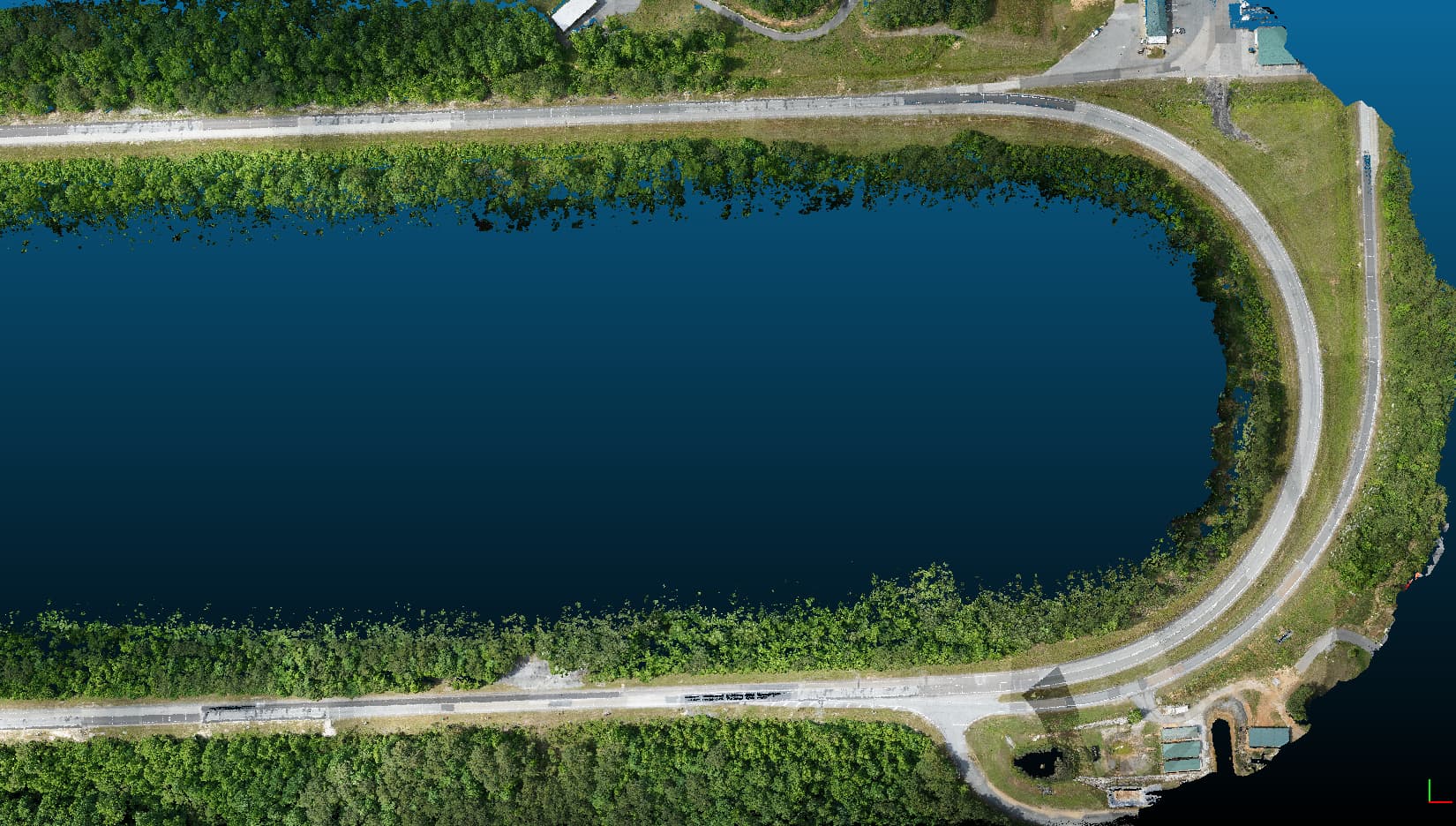
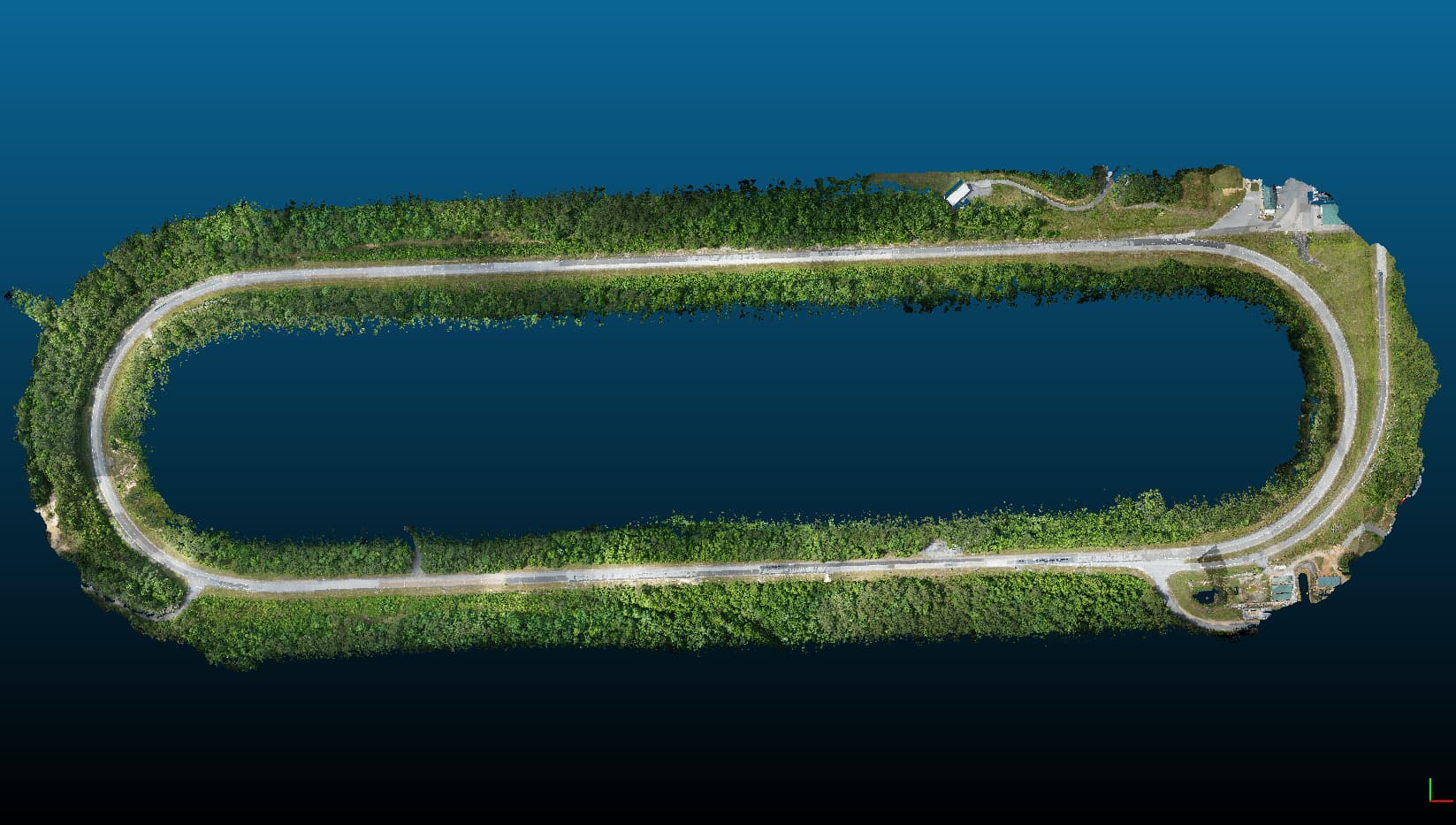
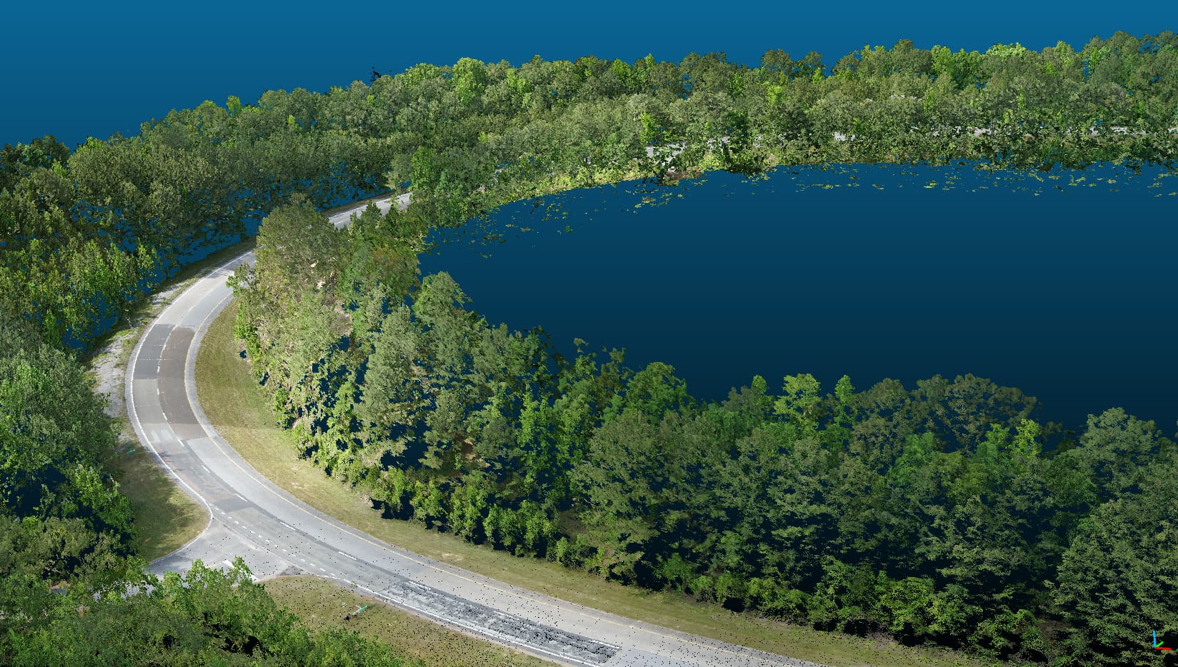
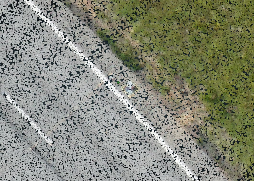
Happy to show off a few screengrabs from this weekends oval track LiDAR mission! It came out fantastic. Harrison’s excellent training videos was a huge help. The R2A was super easy to setup and use on the DJI M300 platform. I setup a Linear mission in the DJI Pilot 2 on the RC. The mission was a bit over 9 minutes. Amazing!

Sweet model!
Its looks good. 
1 Like
Thanks for all your assistance @FlyingRadioWaves! Worked out perfect.
1 Like
This is fantastic! I love to see the community come together!
How low/slow did you fly? How do the cracks in the pavement look? Try messing with the intensity view sliders to get them to pop!
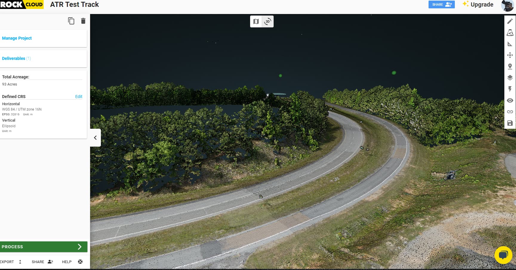
I uploaded the colorized .LAS and photos to my trial cloud account. I defined my CRS as:
Horizontal - WGS 84 / UTM zone 16N
EPSG: 32616 Unit: m
Vertical - Ellipsoid Unit: m.
I then uploaded GCP’s. this is what I see:
My GCP’s are way above my LiDAR dataset. If I re-project to the GCP’s SRS:
(6355 Horizontal, 5703 Vertical) the GCP’s disappear entirely.
What am I doing incorrectly here??
Thanks!
I also tried “Auto Align to GCP”. Any one of the nine GCP’s I use, the remaining GCP’s are off by various amounts:
Hey there! Sounds like a coordinate system issue. Did you mean for your state plane to be in meters and height in Geo12B? Usually that height difference is either a meters/feet thing or a Geoid issue.
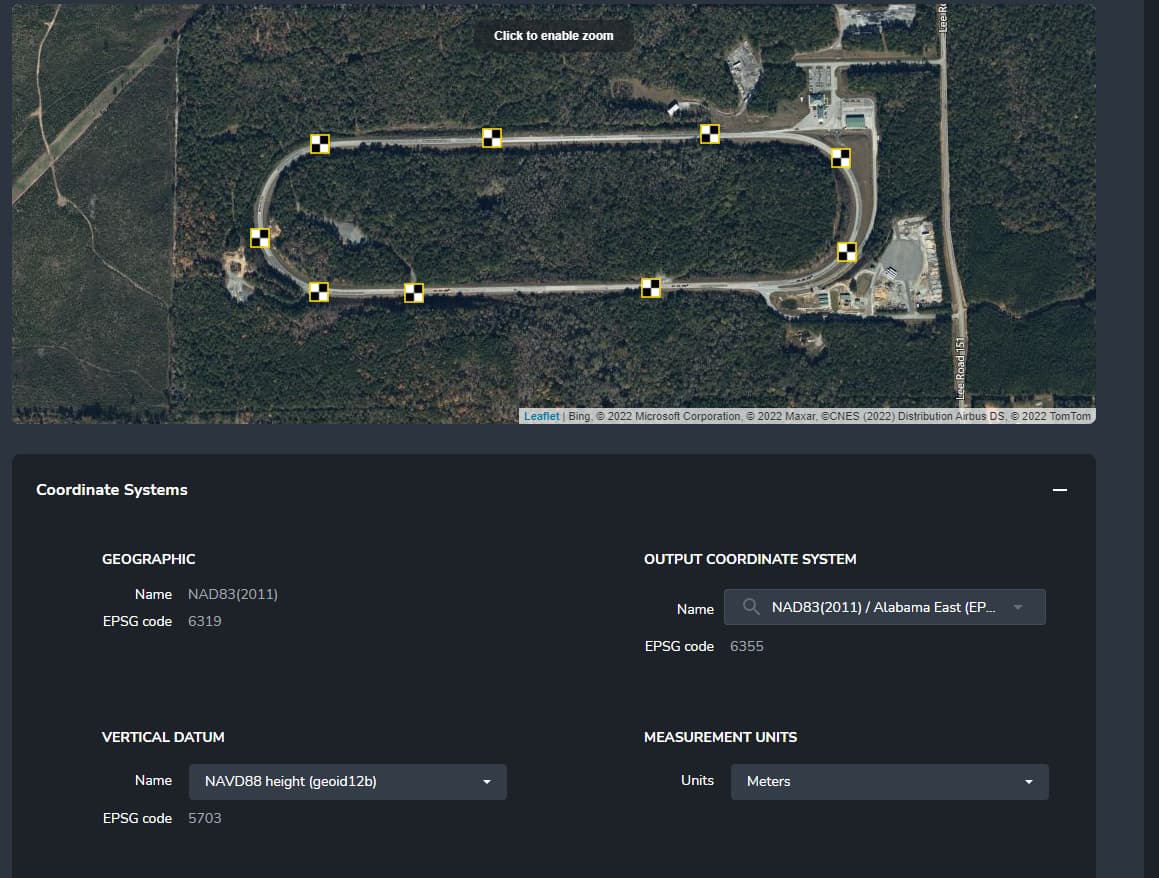
Daniel, Thanks for the reply. My Propeller Aeropoints are exported out with the settings above - NAD83 (2011) Alabama East EPSG:6355 (meters), and a vertical datum of NAVD88 geoid12b EPSG:5703 (meters). When I re-project in Rock Cloud, I see this:
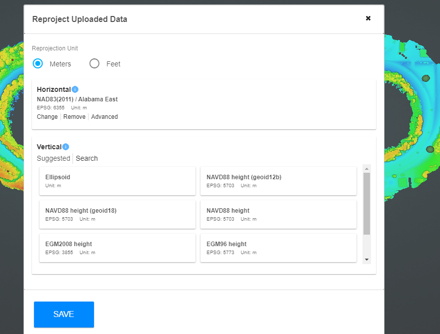
Which should I be picking? Match the Aeropoints SRS or something else??
Thank you!
Another question - Should my GCP’s be lined up with my LiDAR before reprojection? Right now (before reprojection) the GCP’s are 90 meters above the LiDAR.
Step One: Match your Aeropoints chosen coordinate system using Rock’s re-projection tool.
- Now, everything, x,y … should be in alignment with your aeropoints.
- If you don’t reproject your data from the “vanilla” flavor we fly our R2A with, you will have problems.
- Like Mr. Daniel says, this is a coordinate issue.
Step Two: Upload your Aeropoint’s CSV to the Rock Cloud… make double sure you only have 4 columns and pay attention to your northings and eastings. Rock prefers eastings first.
- Define your coordinate system… make sure everything is the same.
- You MUST re-project to your chosen coordinate system before you load your CSV… (but you already got here…)
Step Three: OMG… my elevations are off. Yes, they are off. They always are. Don’t let that freak you out, it will always be off. That is why we have GCPs.
- Use your Adjustment Tool in the Rock cloud. Look at your CSV point, create a measurement beside it, calc the difference and move the model accordingly.
- Check. Move again. Check. You will be getting close.
Step Four: Now that you think you are close, check the other GCPs and they should be the same, or inside your tolerance. We have “golf ball” tolerance, typically 25mm.
If you data is good, you should see similar deltas between the gcps and the lidar. If you don’t, you data may have other problems (bad gps, bad processing, poor data collection, bad luck day…)
Make sure you download YOUR adjusted point cloud.
Enjoy.
1 Like
Great write up!
Don’t forget in Step 3 that you can use Auto Align GCP first to cut down on manual tweaking. I used to spend several minutes moving it a little this way or that way before that awesome tool! Now I just auto align, then tweak it a little bit for things like aeropoints being slightly above ground, etc.