GCP accuracy in the cloud

I’m attempting to assemble the pieces for my first project in the cloud.

Because of issues that are suspected to be caused by IMU disconnect, we had to re-do 2 major sections of the survey on another day. Therefore the base station was at a slightly different location but there is some overlap of point clouds.

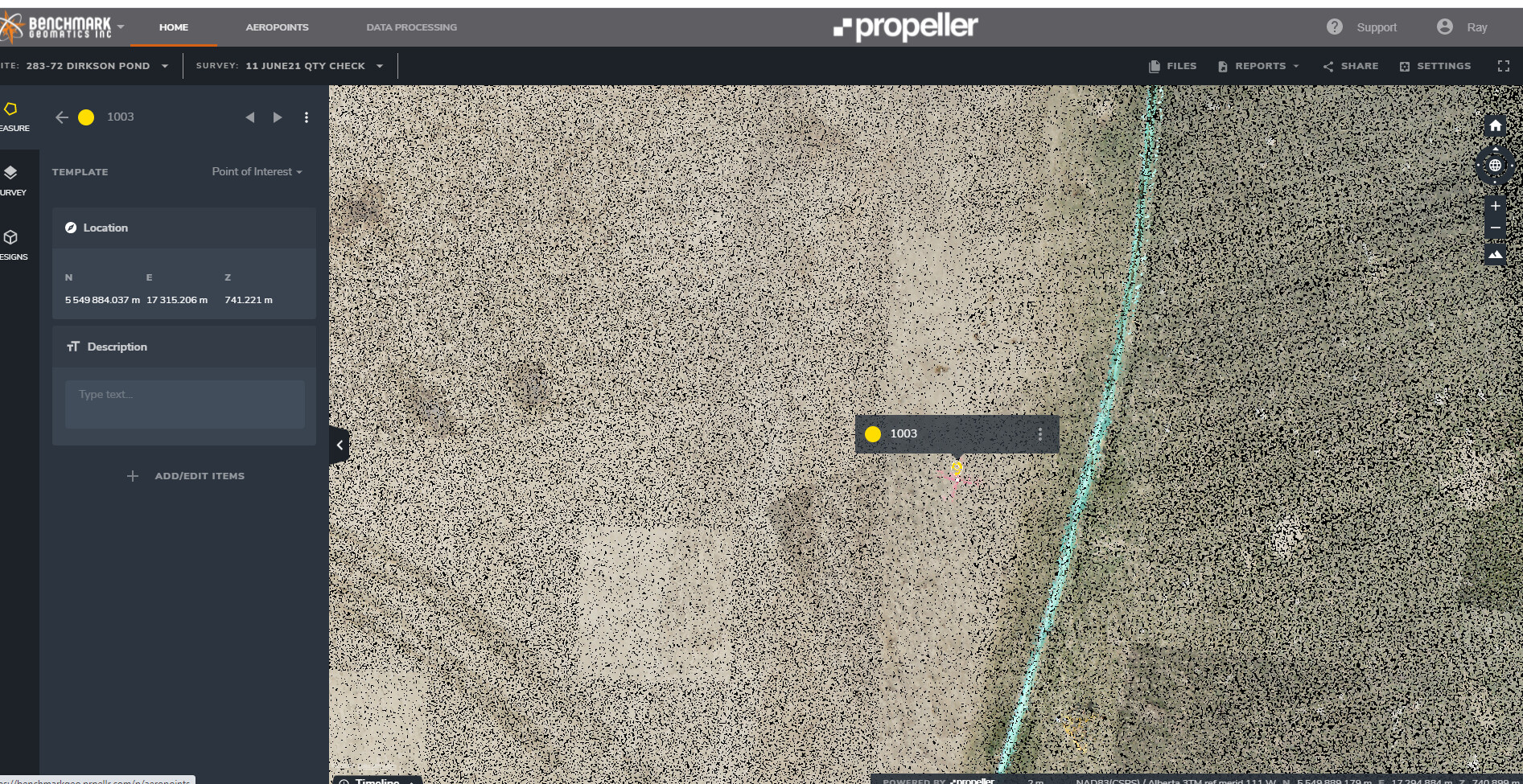
I processed and uploaded a 180 acre section. My antenna height is known, however I didn’t adjust it in PCMaster, I figured I could adjust it in the cloud as per the demonstration videos. I have 2 control points in this area.

https://cloud.rockrobotic.com/share/3ef4e774-df36-4365-a331-254240dba74f

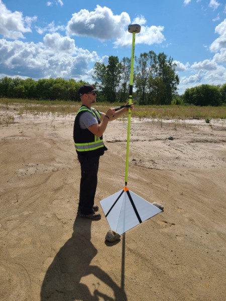
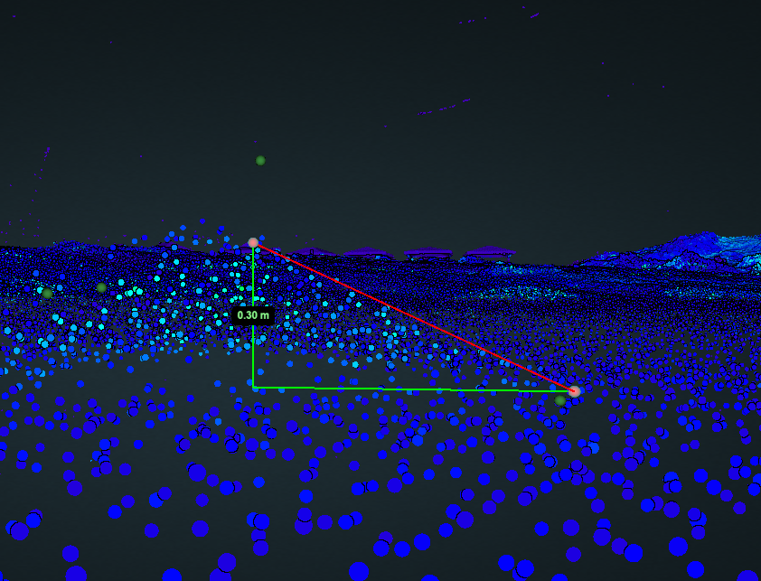
The ground has fairly significant fuzz because the control points were painted on low grass and the flight was performed at 120m AGL … I don’t know how typical this is because this is my first project.
When I adjust the point cloud so that the control points are both within the “fuzz” in the Z direction, the X and Y are still significantly off. If I move the point cloud so one of the control points is as close as I can get it, the other is out in the x,y by a lot (0.7m). (yes, there’s someone parked almost on top of the one control point but there was no way for us to know this before the flight. This was an area we had to re-do the next day because of the IMU issue)
Is this a reprojection error?
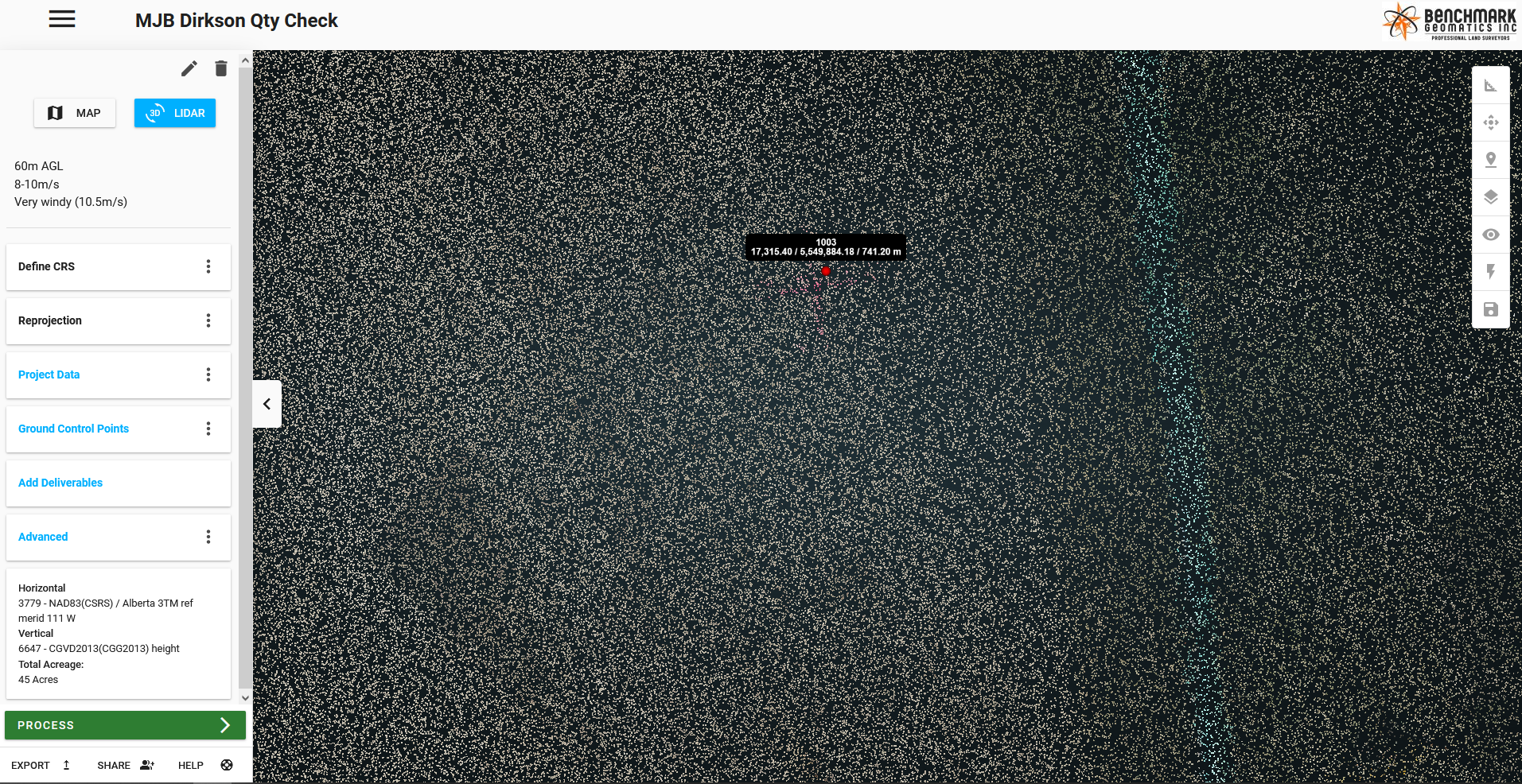
I shot the control points using NAD83(CSRS) / UTM Zone 17N so that’s what I set the reprojection for.
The geoid model that is in the rover we used was the Canadian HT2.0 model. This isn’t available through Rock Cloud as a selection in the vertical datum. It’s supposed to be compatible with CGVD28 which is what I selected. Would this be the cause of the X/Y errors?
Could the errors be caused by the IMU malfunction even on the flights where all the data was gathered?
I’m not sure where other sources of X/Y error crop up… distance from base station? (this was probably around 2.5km at the farthest point) Altitude? is a .7m error in X/Y typical at 120m?
I would like to get this survey as accurate as possible given the circumstances. Any assistance would be greatly appreciated.

The other 3 parts of the survey have some of the same issues as I’m trying to line them up using the compare feature. If they’re lined up on their control points then they don’t line up all that well in the cloud with each other. Close, but not within the error that I was expecting.

@DroneCanada you will want to use “intensity” and not RGB when lining up your GCPs. This is likely the issue. Since intensity parameters are collected at the same moment the laser pulse is returned, these are directly referenced. RGB on the other hand is projected from the photo to the LiDAR points and therefore will not be nearly as accurate. Give that a try and see how it lines up.

1 Like

Unfortunately, with “intensity” I can’t see the GCPs at all. No matter where I move the sliders, the paint doesn’t show up differently than the grass.

I ran into this same problem and the solution was to not use paint on grass anymore. It’s frustrating, I know.

1 Like

The best GCP is a 1m x 1m cross or X made up of black and white paint. We use pieces of plywood painted and put those on the ground. It all has to do with reflectivity.

Regarding the mis-alignment of the x,y… we are experiencing this also.
I believe it has to do with the fact that we are unable to create the “vanilla” data that Rock wants… all I have available is the NAD83(CSRS)/UTM Zone 12N… well, long story short, the CSRS DOES NOT work with the “classic” NAD83… I have data sets that are off by the amount you mention (that’s what caught my eye) and it owes to the difference in the projections between NAD83 and NAD83 CSRS. It’s subtle, but enough to whack things up when you are placing sanitary manholes on a large project! Ask me how I know…
Same with the “ellipsoid”. I know which “ellipsoid”, but there are a few. All of them are off. I can get my data collector to agree with Natural Resources Canada, but never with Rock. I just gave up on getting any type of accuracy on the “z”.

As for the x,y shift… I am trying to find something in my Canadian data collector, which references Canadian corrections stations (Canada’s “OPUS”), which, by Canadian Legislation, MUST transmit the corrections in CSRS with the 2013 vert. datum. This is not what Rock wants for the Lidar.

It is my suspicion, America still being on Nav88, which is like Nad83, similar to WGS84, which I can only measure using a station transmitting NAD83 CSRS, … is creating these input problems for us? We are simply on the next level of geodesy?

I do hope our Engineers at Rock can figure out how to bring “generic” data, no matter what flavor, to work on the front end. This would solve many headaches and make the machine data easier to manage/feed.

@FlyingRadioWaves What antenna are you using for your base station?

@FlyingRadioWaves can you send an example project where you are seeing this issue?

We are using a Spectra Precision SP80 for our base.

Please refer to Lidar job#1798. You can look at my 6 GCPs… they are all just “off” the mark.

I checked the point cloud out in Propeller by placing my marker ON the point


And compared it to Rock…

You can see the difference quite easily.

Propeller: x: 17,315.206 y: 5,549,884.037
Rock (using the coordinates shot in the field): x: 17.315.40 y: 5,549,884.18

Quite the difference. It really mirrors the difference we found comparing Nad83 to Nad83(CSRS) on some of our other projects.

Here is a summary of what I am thinking:

WE have recorded an object on earth in 1928, which we will call “Evidence”. This is a fixed, permanent mark. Our location, as defined by the “local” coordinate system is 5000, 5000. We also know our Lat/Long on this point, which we can derive mathematically from our coordinate conversions, or just look on the map… and this point will translate to (for example) 49°01’01", -110°01’01". Always. This is math… that coordinate, no matter, will always translate back to that Lat/Long.

WE return 100 years later. WE’ve had a quantum leap in technology and how we measure coordinates and how we “realize” and model our awesome planet. After much work and math, Natural Resources Canada discovered a new model for Canada, realized as the Canadian Spatial Reference System. This update transformed how we record our x,y and our z values, based on all the new things our technology has let us discover!

So here we are, at “Evidence”. We will take a check shot on “Evidence”. Wow… it is at 5000,5000. All is good! BUT NO!! Our continent has drifted and changed along with how we measure our position on earth (GNSS!!). And when I complete the mathematical coordinate transformation on my point, “Evidence”, which is still at 5000,5000… the conversion will come out to 49°01’01"…, because the math did not change… but the physical location did.

So, if my correction beacon ONLY transmits corrections in CSRS, it is seeing the coordinate of 5000,5000 and assigning it the converted Lat/Long… or, it hears the Lat/Long and the same conversion works both ways… now I am at 5000,5000 in the CSRS measurement.

I will never match Rock Robotic’s request to present the data in WGS84 they way they want it, because our recording of WGS84 is based in our CSRS, versus the American Nad88 version of WGS84 (which was our OLD Nad83 and similar to our older Nad27).

That’s just an idea to explain why, no matter what coordinate system, geoid, ellipsoid or flavor of the day I use… I will never match. I can shift and correct my received data in post processing, thankfully, but I don’t think it will come from the Lidar, yet.

Am I thinking correctly?

When you say that you’re correcting in post, do you mean in the rock cloud or are you making adjustments before uploading? Thank you for your investigation into this, I’m still working out our methods / operating procedures and I was trying to figure out the discrepancies.

I did a photogrammetry operation with a dozen control points and then ran the same area on 1 battery with the R2A. (covered 80% of the same area) and I have them up in the rock cloud. My control points aren’t ideal so I was going to do it again on another site before really making any measurements. What i found was the photogrammetry cloud (processed in pix4d) output in NAD83(CSRS) / UTM Zone 17N was off by a significant amount compared to the reprojection in the Rock Cloud of the lidar data in the same datum.

The post processing adjustments are completed in the Rock Cloud.

My photogrammetry is processed in Propeller. When I started with Propeller, I had the same issue with my GCPs not lining up. There was much weeping and gnashing of teeth until it was realized that the data was being processed using the American system… once they adopted the corrections from Canada, everything came into focus and we were only out millimeters (and then I could create whatever flavor of coordinates I wanted).

1 Like

I have also seen differences in Pix4D output compared to my LiDAR georeference output - using the “same” coordinate system. I have to move the ortho aerial (from pix) to match the lidar point cloud. The first time it was difficult because it can be hard to see the targets in the cloud. But now I know what the shift is for that particular CS.

Try using metal tape on the targets

I’ve just completed a survey and I need some help with accuracy and control points.

In the surveys I’ve done so far, I learned the hard way early on about painted x’s not being ideal for lidar. I purchased some white/black checkered control points that lay flat on the ground and they do work somewhat better, however finding the exact centre is still pretty hard to accomplish. After doing some searching for a better alternative, I found a paper online that described 3 sided pyramid shaped control points. We built several of them and used them on the most recent project.

They are 1m along each base side and ~41cm tall

I 3D printed a little cap for the top so that we could measure the location.

On most of them, we also measured the point at the ground at one of the points.

They are much easier to see in the point cloud as we can use the 3D shape to determine the top point.

https://cloud.rockrobotic.com/share/bbd641ef-7cf8-4fed-ac17-5864d9f47ba2

The measured control points are as they should be – approximately 41-44 cm different in elevation. (The cap adds a little and the point sunk into the ground a little below) In the point cloud, however, the points don’t seem to line up.

If I align the ground to the lower measured point, The higher point appears to be significantly higher than the pyramid. The pyramid only appears to be ~30 cm tall in the point cloud.

The ground point doesn’t seem to align with the point of the pyramid on the ground either. It all feels like guessing with several cm of potential error in any direction.

I have not yet had success with the reprojection lining up x, y, z on any point cloud so far. I understand that the point cloud will always have some “fuzz” and that elevations will have some error within that. The X, Y, is a lot trickier for me as I can’t find the center of a control point to any more than a guess in the general area.

@DroneCanada This is what we use for GCPs: What material should be used for your ground control points?

From the picture you supplied the black stripe is quite a bit smaller and difficult to pick up in intensity view. That being said, we have not extensively tested pyramid shaped GCPs. Are you seeing any other height discrepancies within the dataset? I measured some trucks and the width of the double garage in the dataset and they all seem to check out. (certainly not 25% shorter than the objects measured should be)

So the Routescene targets aren’t a recommended approach? Retroreflective tape (not regular reflective tape) should be the ticket. I’m about to start field testing a few versions of GCPs with this applied to better understand the viability. Because our current GCPs seem to be hit or miss. I do agree with the premise of what 0P is saying. If I line up at target in one place and go look at any of the other targets they are off-center. I end up taking a best-guess adjustment in Rock Cloud.

@RSI_Eric I would not recommend retroreflective tape. You will likely get very poor results when the sun is behind the sensor in the sky. (Lots of sun reflection causing false returns). Black and white checkerboard has beed great for us.